5 Minutes To Understand The Optical Delay Line
The element or device used to delay an electrical signal for some time is called a delay line. In recent years, with the rapid development of the electronic industry, such components are widely used in more precise oscilloscopes, color TVs, electronic computers, industrial process control, modern radar systems, and other fields. With the continuous updating and development of technology, the optical delay line is now commonly used. This delay line has higher efficiency and is very cheap.
What is an Optical Delay Line?
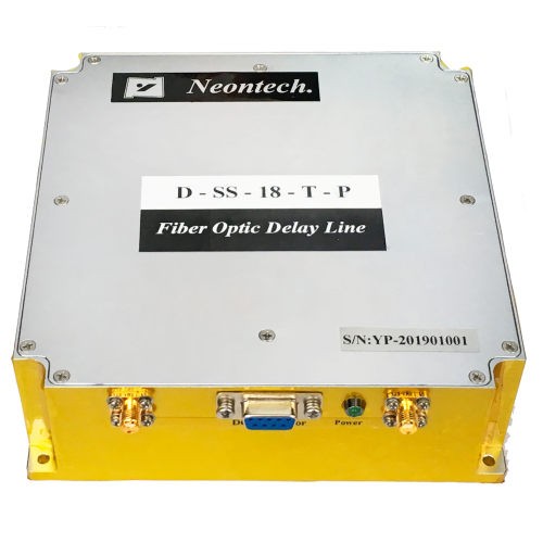
The element or device used to delay an electrical signal for some time is called an optical delay line. The delay line should have flat amplitude-frequency characteristics and certain phase-shift characteristics (or delay-frequency characteristics) in the passband, with appropriate matching impedance and small attenuation. For analog signals, inductance and capacitance are generally used, or coaxial cables and spirals are used directly; digital signals also use charge-coupled devices or surface acoustic wave devices.
Delay lines are mainly divided into electromagnetic delay lines and ultrasonic delay lines. The delay of the electromagnetic delay line is from a few nanoseconds to tens of microseconds, and the amplitude-frequency characteristics are mostly low-pass. The delay of the ultrasonic delay line is from several microseconds to several thousand microseconds, the amplitude-frequency characteristic is band-pass type, and the center frequency can reach more than several hundred megahertz.
The development of the delay line is relatively mature, the process is simple, the price is low, and it is widely used. Ultrasonic delay lines, especially surface acoustic wave delay lines, are constantly being developed to serve a variety of purposes. In terms of characteristics and use, the two types of delay lines have their strengths and complement each other.
Classification of Optical Delay Lines
Bulk Acoustic Delay Line
The bulk acoustic wave microwave delay line uses crystal rods and sheets as sound transmission media and is composed of thin-film transducers and matching networks that convert electrical (acoustic) signals into acoustic (electrical) signals on the end faces of the rods and sheets.
The microwave electrical signal is coupled to the input transducer through the matching network, converted into a microwave acoustic signal, and propagated in the medium at the speed of sound, the output transducer converts the acoustic signal into an electrical signal, and the delayed microwave signal is obtained through the output matching network. The length of the delay time depends on the length of the acoustic medium.
Compared with the coaxial cable delay line, the bulk acoustic wave microwave delay line has the characteristics of small size, lightweight, no dispersion, small delay temperature change, and low loss. It can be widely used in radar, aircraft, missile target signal simulation, electronic countermeasures, electronic ignition, frequency discrimination, moving target display, altimeter calibration, and other systems.
Optical Fiber, Optical Waveguide Delay Line
To improve the anti-interference ability, resolution, and identification ability and solve the problem of multi-target imaging, it is required that the phased array radar must have as large an instantaneous bandwidth as possible; to solve the limitation of the instantaneous bandwidth of the signal caused by the aperture effect, the Delay line for delay compensation.
The traditional coaxial delay line, surface acoustic wave delay line, and charge combination device can not meet the high-resolution requirements of radar systems. Now, optical delay technology is used. The most common and mature technology is the optical fiber delay line. application.
Optical fiber is an excellent medium for generating delay and realizing signal distribution requirements. Optical fiber delay lines have the advantages of long-term (tens of microseconds) storage of large-bandwidth analog signals (tens of gigahertz), low loss, wide bandwidth, etc., and dynamic range. Large, the three-transition signal is small, it is quite easy to implement a delay line, in addition to anti-interference, lightweight, small size, which is particularly important for airborne applications.
The optical waveguide delay line can also achieve a large instantaneous bandwidth and improve the anti-jamming capability, discrimination, identification, and multi-target imaging capabilities of the radar system. Compared with the optical fiber delay line, the optical waveguide delay line has the following advantages: higher delay accuracy, High operating frequency; low loss per unit length; small size, lightweight, strong anti-electromagnetic interference ability; high degree of integration; the use of polymer materials also has the advantages of low dielectric constant, high electro-optic coefficient, and high thermo-optic coefficient.
Superconducting Microwave Delay Line
The surface resistivity of high-temperature superconductors is very low, which reduces the dispersion effect caused by conductor loss, and the existence of dynamic inductance makes high-temperature superconducting transmission lines exhibit a diffuse wave effect, which makes them have specific advantages in the field of delay lines.
The research on superconducting delay lines can be roughly divided into two categories: one
The class is to use a uniform transmission line to realize the time delay of the signal through a meander (serpentine) line structure or a double helix structure.
Another type is a tapped delay line or a chirp filter. The former can realize the delay effect through a microstrip line, a coplanar waveguide, or a stripline structure; the latter uses a cascaded },/4 combined transmission line to achieve reverse-phase transmission, and finally obtains at the reflection port. Signal.
Application Areas of Delay Lines
Acoustic delay lines are suitable for some occasions that require long time delay and high stability. It is known from basic physics that the propagation speed of ultrasonic waves in solids and liquids is about 3 Km/s, which is much slower than that of electric waves in conductors. Based on this principle, converting electrical signals into mechanical vibrations and passing them through conductors can obtain a relatively long delay time. However, the main disadvantages of this type of delay line are difficulty in making a transducer with a relatively flat broadband response, unsatisfactory signal suppression effect, the complex structure of a double-ended transducer, difficulty integration with system devices, and low operating frequency.
Optical fiber delay lines are suitable for pulse coding, decoding, filtering, correlation convolution operations, and A/D conversion of high-frequency digital signals, and optical fiber communication has the advantages of wide bandwidth, low loss, anti-interference, and good confidentiality. The structure of the optical fiber delay line is quite complex and difficult to integrate, and the cost is high.


