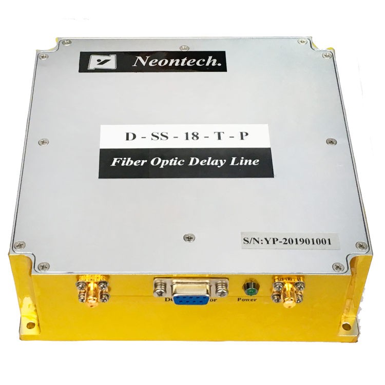
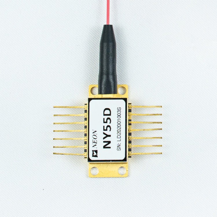
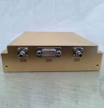
Automotive Radar Calibration Simulator
- Typical series: NY 037 series and NY 059 series.
- Mainly used in the vehicle millimeter wave radar echo simulation system, such as the calibration of the vehicle radar ranging system, driving assistance, anti-collision function, etc. They can also be applied to satellite communication, inter-station transmission, unmanned driving, photoelectric systems (such as lidar, radio frequency radar, etc.), UAV(unmanned aerial vehicle), etc.
- Use optical fiber as the signal delay transmission medium. Advantages: wider carrier bandwidth, stronger anti-interference, better confidentiality, lower system power consumption, smaller volume, lighter weight, and so on.
- The higher-order version of simulators adopts the magneto-optical switch. Compared with the traditional mechanical optical switch, the magneto-optical switch has a faster switching speed, longer service life, and shorter delay step.
- Be adapted to the mainstream industrial control communication protocols, such as the typical RS232, RS422, RS485, SPI, etc.
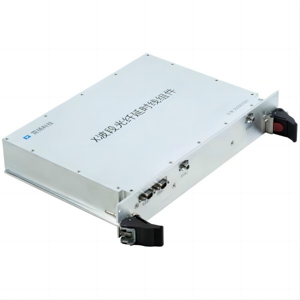
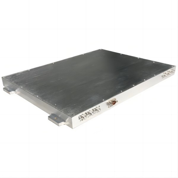
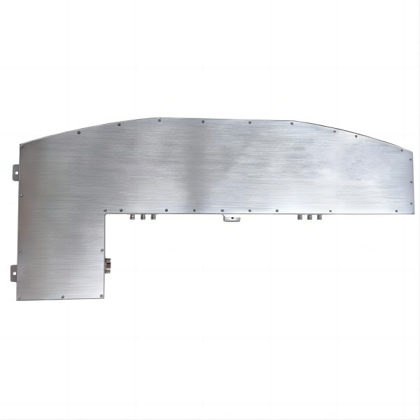
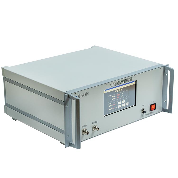
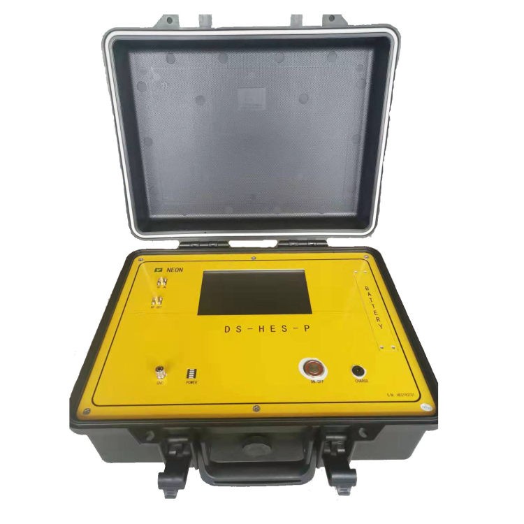
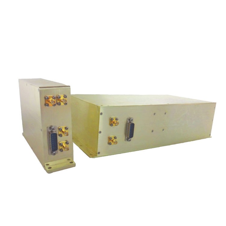
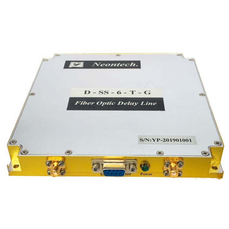
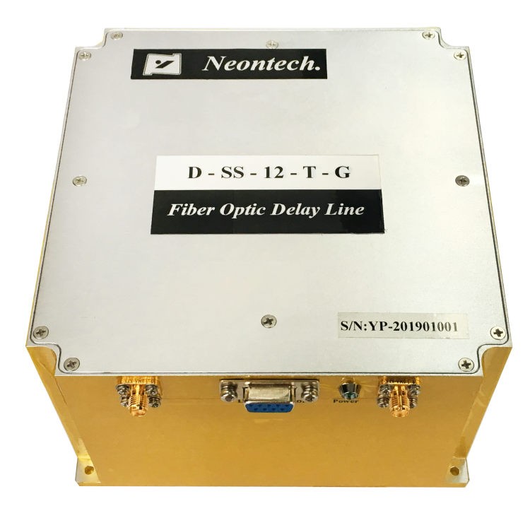
- Types of packages: standard chassis, portable chassis, and core modules.
Feature
- Strong anti-interference
- High simulation range and accuracy
- Fast switching time
- Ultra wideband
Application
- Automotive Electronics
- Radar simulation
- Signal processing
- Electronic War
Operational Principle
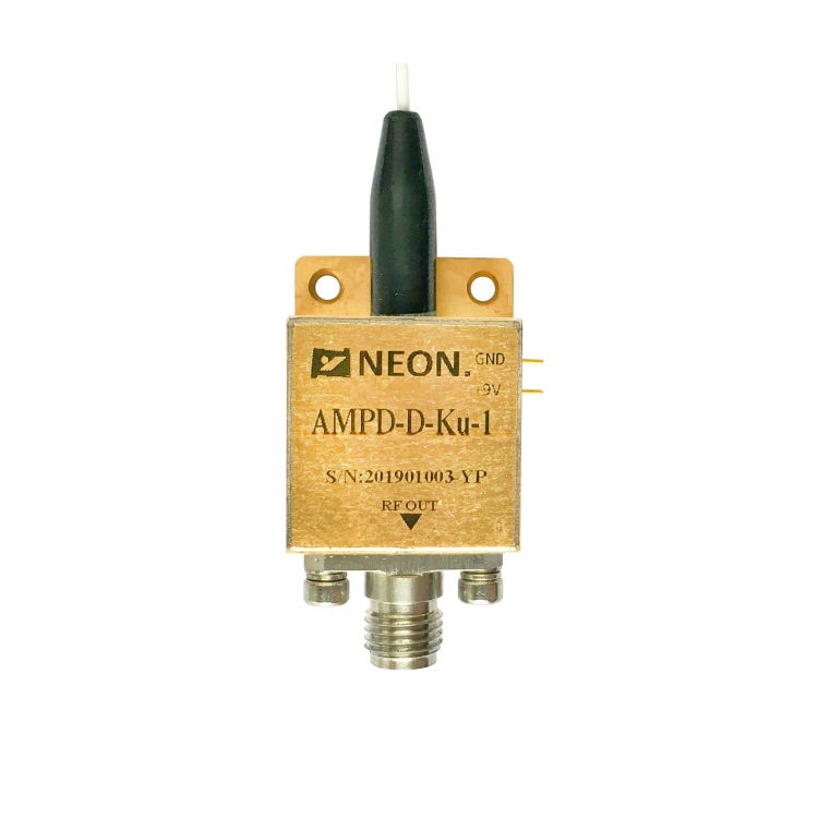
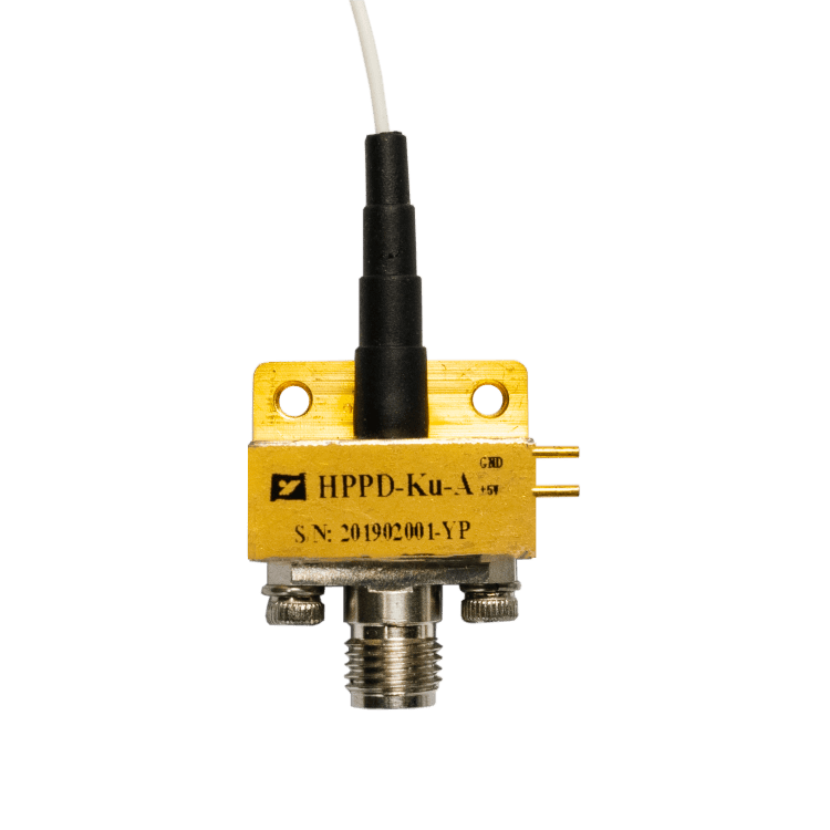
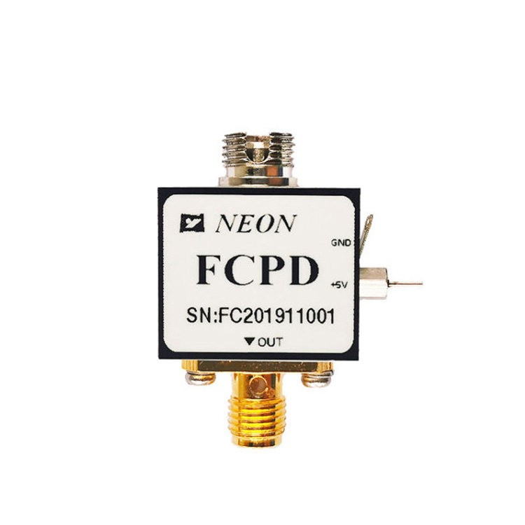
NY 037 and NY 059 series automotive radar calibration simulators are mainly composed of an input/output RF interface, electric/optical converter, delay optical fiber, optical/electric converter, matching amplifier, and delay switching controller. NY 037 series and NY 059 series automotive radar calibration simulators adopt optical fiber delay technology, first to convert the radio frequency signal into a laser signal, and the laser signal for the different delay, and then the laser signal after the delay is reduced to radio frequency signal and output after matching and amplification.
Electrical / Optical Characteristics
NY037-1 Photoelectric parameters
|
Parameter |
Value |
unit |
remarks |
||
|
Min |
Typ |
Max |
|||
|
Frequency |
5.4 |
– |
10.4 |
GHz |
– |
|
Input signal power |
-45 |
– |
-5 |
dBm |
– |
|
In-band amplitude flatness |
– |
– |
±1.5 |
dB |
– |
|
RF insertion loss |
– |
0±1.5 |
– |
dB |
@9.9GHz |
|
In-band spurious signal |
– |
– |
-50 |
dBc |
– |
|
Input VSWR |
– |
– |
2 |
– |
– |
|
Output VSWR |
– |
– |
2 |
– |
– |
|
Fixed delay T0 |
– |
– |
3 |
ns |
Including all the frequency points in the 5G band |
|
Time delay |
T0 |
– |
2048+T0 |
ns |
– |
|
Time delay step |
– |
0.5 |
– |
ns |
– |
|
Time delay accuracy |
– |
±0.1 |
– |
ns |
10ns and less |
|
– |
±0.2 |
– |
ns |
10 ns to 1000 ns |
|
|
– |
±0.3 |
– |
ns |
More than 1000ns |
|
|
Fixed altitude H0 |
– |
– |
0.45 |
ns |
Including all the frequency points in the 5G band |
|
Altitude range |
H0 |
– |
307.2+H0 |
m |
– |
|
Altitude step |
– |
0.075 |
– |
m |
– |
|
Altitude accuracy |
– |
0.015 |
– |
m |
1.5 m and below |
|
– |
0.03 |
– |
m |
From 1.5 m to 150 m |
|
|
– |
0.045 |
– |
m |
More than 150m meters |
|
|
Switch time |
– |
– |
5 |
ms |
– |
|
Switch life |
3*10^8 |
– |
– |
Times |
– |
|
Working temperature |
10 |
– |
55 |
°C |
– |
NY037-2 Photoelectric parameters
| Parameter | Value | Unit | Remarks | ||
| Min | Typ | Max | |||
| Frequency | 5.4 | – | 10.4 | GHz | – |
| Input signal power | -45 | – | -5 | dBm | – |
| In-band amplitude flatness | – | – | ±1.8 | dB | – |
| RF insertion loss | – | 0±1.5 | – | dB | @9.9GHz |
| In-band spurious signal | – | – | -50 | dBc | – |
| Input VSWR | – | – | 2 | Ω | – |
| Output VSWR | – | – | 2 | dBc | – |
| Fixed delay T0 | – | – | 3.5 | ns | Including all the frequency points in the 5G band |
| Time delay | T0 | – | 2047.5+T0 | ns | – |
| Time delay step | – | 0.5 | – | ns | – |
| Time delay accuracy | – | ±0.1 | – | ns | 10ns and less |
| – | ±0.2 | – | ns | 10 ns to 1000 ns | |
| – | ±0.3 | – | ns | More than 1000ns | |
| Fixed altitude H0 | – | – | 0.525 | ns | Including all the frequency points in the 5G band |
| Altitude range | H0 | – | 307.125+H0 | m | – |
| Altitude step | – | 0.075 | – | m | – |
| Altitude accuracy | – | 0.015 | – | m | 1.5 m and below |
| – | 0.03 | – | m | 1.5 m to 150 m | |
| – | 0.045 | – | m | More than 150m meters | |
| Switch time | – | – | 100 | us | – |
| Switch life | 3*10^8 | – | – | Times | – |
| Working temperature | 10 | – | 55 | °C | – |
| Storage temperature | -20 | – | 70 | °C | – |
| Voltage | – | ±5 | – | V | – |
| Control method | RS-485 | ||||
| RF connector | SMA-K | ||||
NY037-3 Photoelectric parameters
| Parameter | Value | Unit | Remarks | ||
| Min | Typ | Max | |||
| Frequency | 5.4 | – | 10.4 | GHz | – |
| Input signal power | -45 | – | -5 | dBm | – |
| In-band amplitude flatness | – | – | ±1.8 | dB | – |
| RF insertion loss | – | 12±1.5 | – | dB | @9.9GHz |
| In-band spurious signal | – | – | -50 | dBc | – |
| Input VSWR | – | – | 2 | Ω | – |
| Output VSWR | – | – | 2 | dBc | – |
| Fixed delay T0 | – | – | 5 | ns | Including all the frequency points in the 5G band |
| Time delay | T0 | – | 4096+T0 | ns | – |
| Time delay step | – | 0.25 | – | ns | – |
| Time delay accuracy | – | ±0.1 | – | ns | 10ns and less |
| – | ±0.2 | – | ns | 10 ns to 1000 ns | |
| – | ±0.3 | – | ns | 1000 ns to 2048 ns | |
| – | ±0.5 | – | ns | Over 2048ns | |
| Fixed altitude H0 | – | – | 0.075 | ns | Including all the frequency points in the 5G band |
| Altitude range | H0 | – | 614.4+H0 | m | – |
| Altitude step | – | 0.0375 | – | m | – |
| Altitude accuracy | – | 0.015 | – | m | 1.5 m and below |
| – | 0.03 | – | m | 1.5 m to 150 m | |
| – | 0.045 | – | m | 150 m to 307.2 m | |
| – | 0.075 | – | m | Above 307.2 m | |
| Switch time | – | – | 100 | us | – |
| Switch life | 3*10^8 | – | – | Times | – |
| Working temperature | 10 | – | 55 | °C | – |
| Storage temperature | -20 | – | 70 | °C | – |
| Voltage | – | ±5 | – | V | – |
| Control method | RS-485 | ||||
| RF connector | SMA-K | ||||
Typical Curve for NY037 series
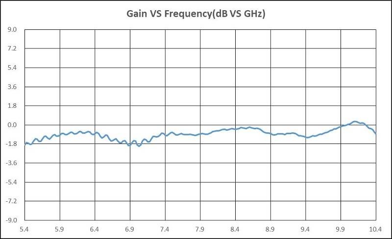
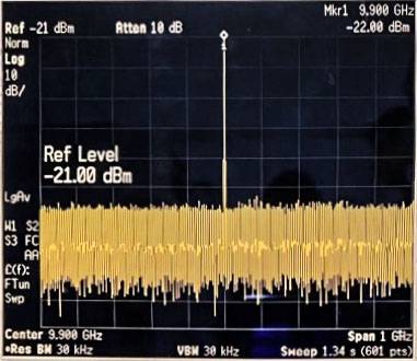
Electrical / Optical Characteristics
NY059-1 Photoelectric parameters
| Parameter | Value | Unit | Remarks | ||
| Min | Typ | Max | |||
| Frequency | 4 | – | 12 | GHz | – |
| Input signal power | -45 | – | -5 | dBm | – |
| In-band amplitude flatness | – | – | ±1 | dB | In 500 MHz |
| In-band power stability | – | – | ±1 | dB | -20℃/2h,0℃/2h,20℃/2h,40℃/2h |
| RF input power | -18 | – | 16 | dBm | – |
| RF input fire-resistant power | 25 | – | – | dBm | – |
| Gain of Input and output | -5 | – | – | dB | – |
| Crosstalk | – | – | 50 | dB | – |
| Fixed delay T0 | 3.5 | – | 15 | ns | – |
| Time delay | T0 | – | 10.23+T0 | us | – |
| Time delay step | – | 10 | – | ns | – |
| Time delay accuracy | – | ±0.5 | – | ns | – |
| Fixed altitude H0 | 0.525 | – | 2.25 | ns | – |
| Altitude range | H0 | – | 1534.5+H0 | m | – |
| Altitude step | – | 1.5 | – | m | – |
| Altitude accuracy | – | 0.075 | – | m | – |
| Switch time | – | – | 0.8 | ms | – |
| Switch life | 3*10^8 | – | – | Times | – |
| Working temperature | -10 | – | 45 | °C | – |
| Storage temperature | -20 | Switch | 65 | °C | – |
| Voltage | – | ±12 | – | V | – |
| Current | – | – | 1.5 | A | – |
| Control method | SPI | ||||
| Control interface | J30J-9ZKP | ||||
| Power supply interface | J30J-9ZKP | ||||
NY059-2 Photoelectric parameters
| Parameter | Value | Unit | Remarks | ||
| Min | Typ | Max | |||
| Frequency | 8 | – | 12 | GHz | – |
| In-band amplitude flatness | – | – | ±1.5 | dB | In 1,000 MHz |
| RF input power | -18 | – | 16 | dBm | – |
| RF input fire-resistant power | 20 | – | – | dBm | – |
| Gain of Input and output | -5 | – | – | dB | – |
| Crosstalk | – | – | 50 | dB | – |
| Fixed delay T0 | – | – | 20 | ns | – |
| Time delay | T0 | – | 4+T0 | us | – |
| Time delay step | – | ±1 | – | ns | – |
| Time delay accuracy | – | 1 | – | ns | – |
| Fixed altitude H0 | – | – | 3 | m | – |
| Altitude range | H0 | – | 600+H0 | m | – |
| Altitude step | – | 0.15 | – | m | – |
| Altitude accuracy | – | 0.15 | – | m | – |
| Switch time | – | – | 0.5 | ms | – |
| working temperature | -10 | – | 45 | °C | – |
| storage temperature | -20 | – | 65 | °C | – |
| working voltage | – | ±12 | – | V | – |
| relative humidity | 10 | – | 85 | % | – |
| current | – | – | 1.5 | A | – |
| Output signal | No dispersion | ||||
| Control method | SPI | ||||
| Control interface | J30J-9 ZKP and CPCI connector | ||||
| Power supply interface | J30J-9 ZKP and CPCI connector | ||||
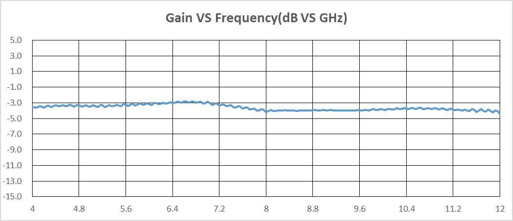
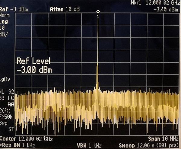
Typical curves for NY059 series
Dimensions and interface
NY037 series
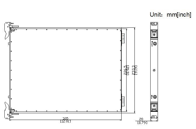
NY 037-1 Dimensions and Interface
|
NY037-1 Interface Definition |
||||
|
Interface |
RF OUT |
RF IN |
Power interface |
Control interface |
|
Interface Type |
SMA-K |
SMA-K |
DB15 |
DB15 |
NY037-2 Dimensions and Interface

|
Definitions of NY037-2 and NY037-3 interfaces |
|||||||
|
Interface |
Transmit Out |
Transmit In |
IF Out |
Receive In |
Receive Out |
IF In |
Power Interface |
|
Interface Type |
SMA-K |
SMA-K |
SMA-K |
SMA-K |
SMA-K |
SMA-K |
J30J-9ZKP |
NY 037-3 Dimensions and interface
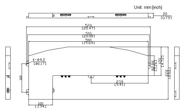
|
Definition of NY037 Series power supply and control interface |
|||
|
Pin number |
Definition |
Pin number |
Definition |
|
1 |
+5VDC |
5 |
RS-485 B |
|
2 |
-5VDC |
6 |
Signal ground |
|
3 |
GND |
7 |
Power to |
|
4 |
RS-485 A |
8、9 |
+5VDC |
|
Connector–socket type |
J30J-9ZKP |
||
|
Connector-plug type |
J30J-9TJL |
||
NY059 seriesDimensions and interface

Definition of NY059 series power supply and control interface
|
Power interface |
SPI control interface |
||
|
Pin number |
Definition |
Pin number |
Definition |
|
1~4 |
+12VDC |
1 |
SCLK |
|
5 |
NC |
2 |
Din(SDI) |
|
6~9 |
GND |
3 |
LE(CS) |
|
– |
– |
4 |
GND |
|
– |
– |
5~9 |
NC |
|
Connector-socket type |
J30J 9ZKP |
Connector-socket type |
J30J-9ZKP |
|
Connector-plug type |
J30J-9TJL |
Connector-plug type |
J30J-9TJL |
This series of products are customized, and the product information in this article is for reference only


