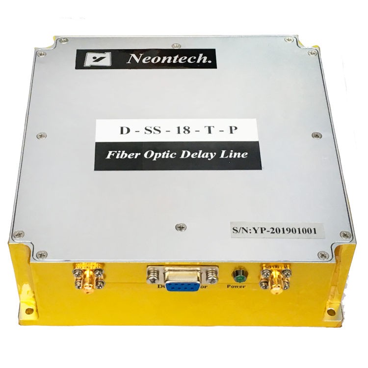
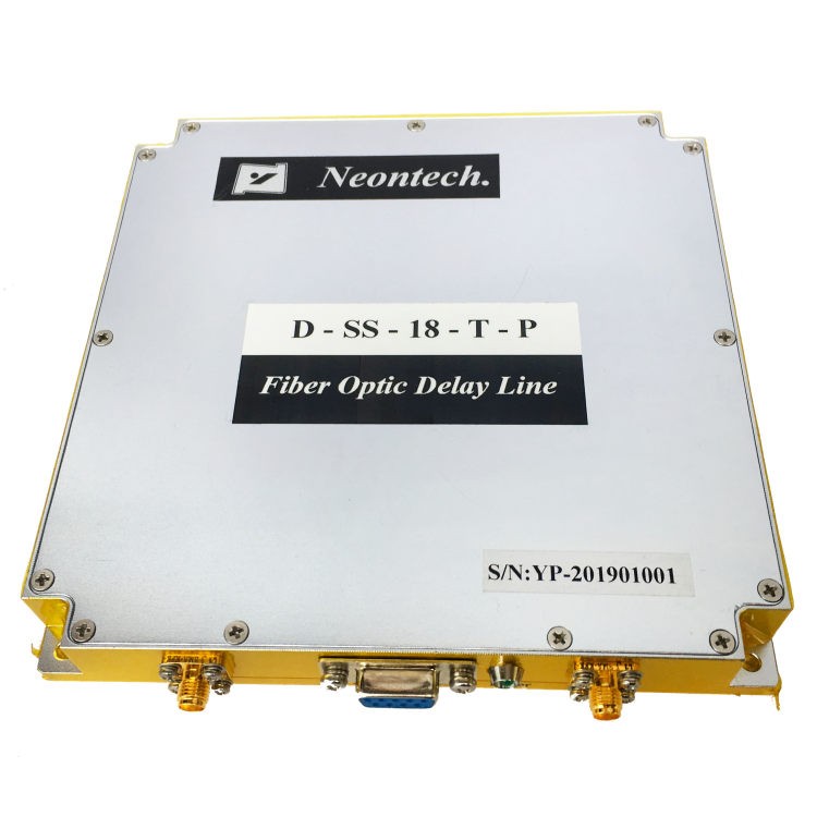
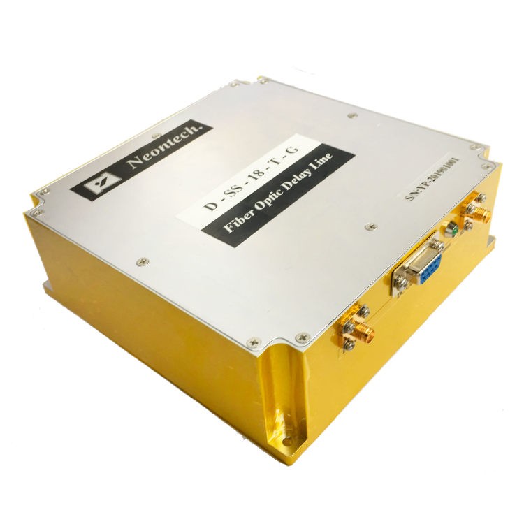
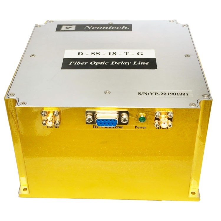
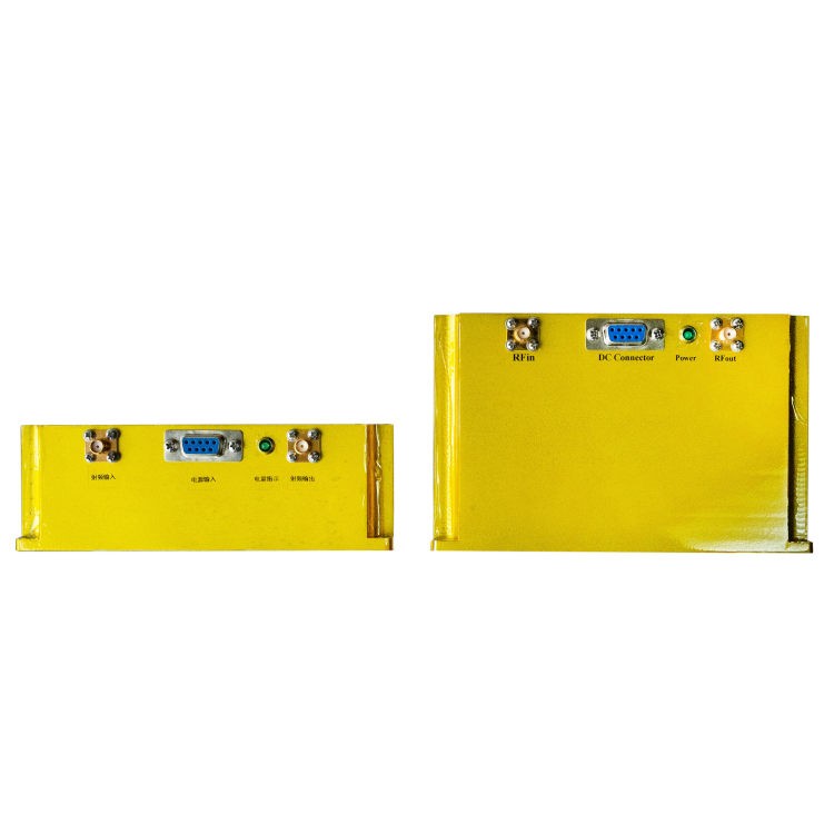
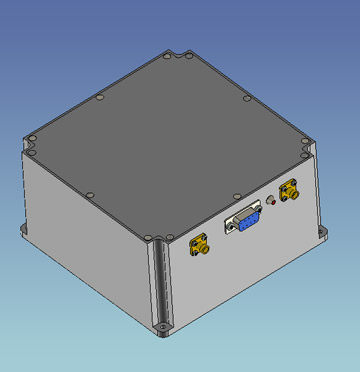
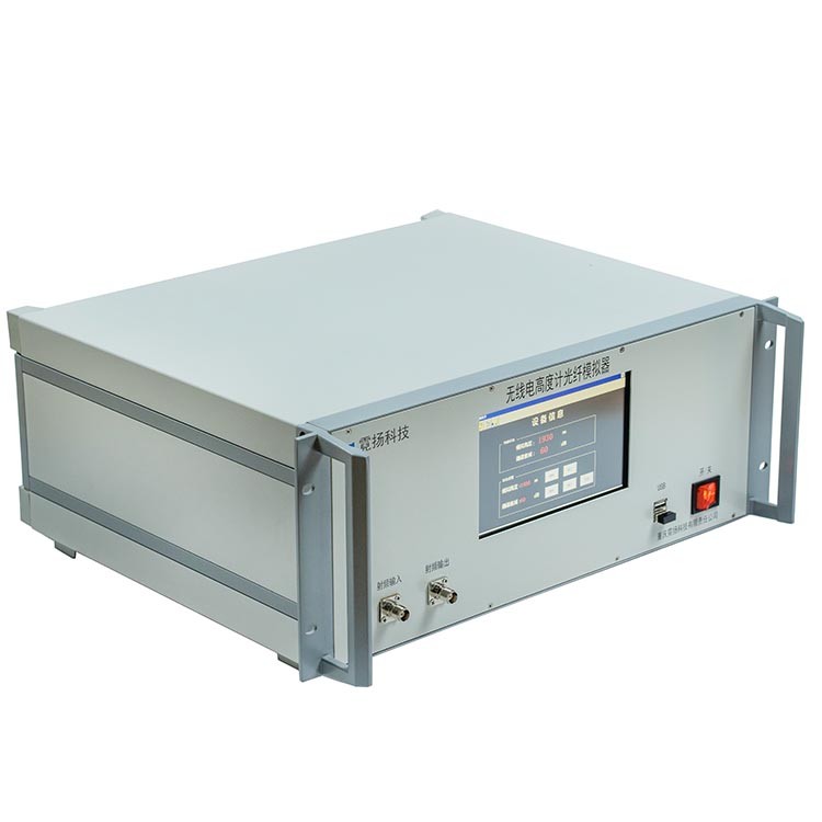
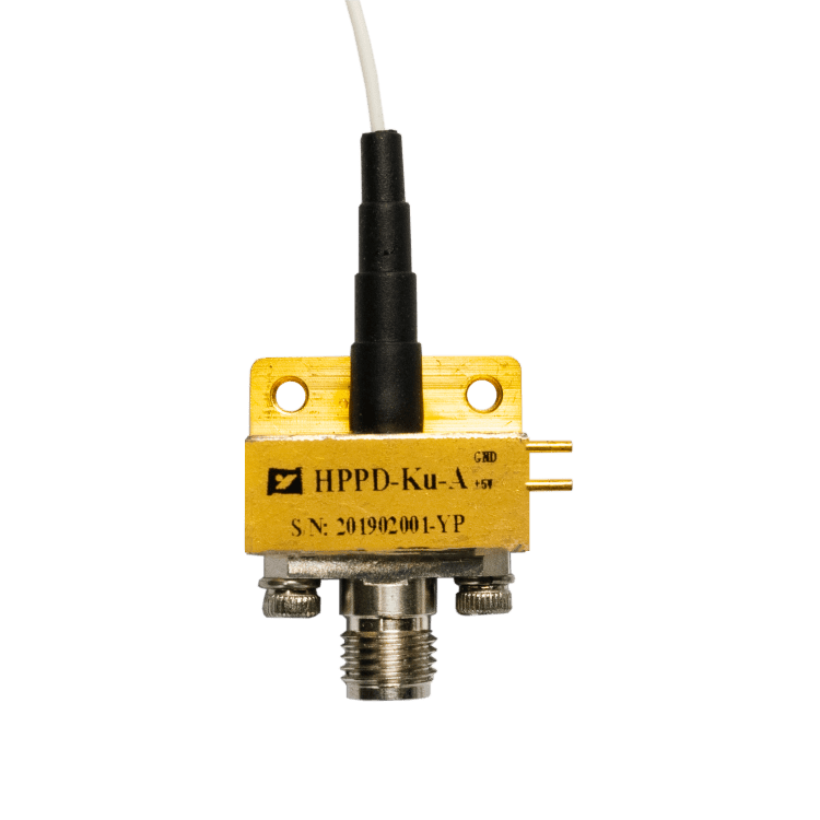
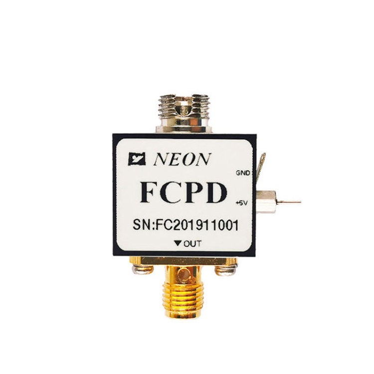
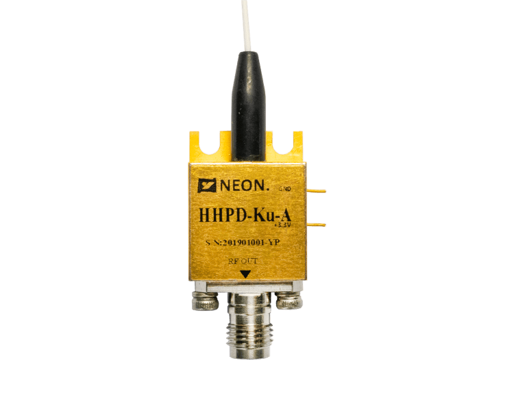
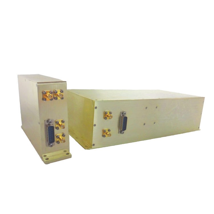
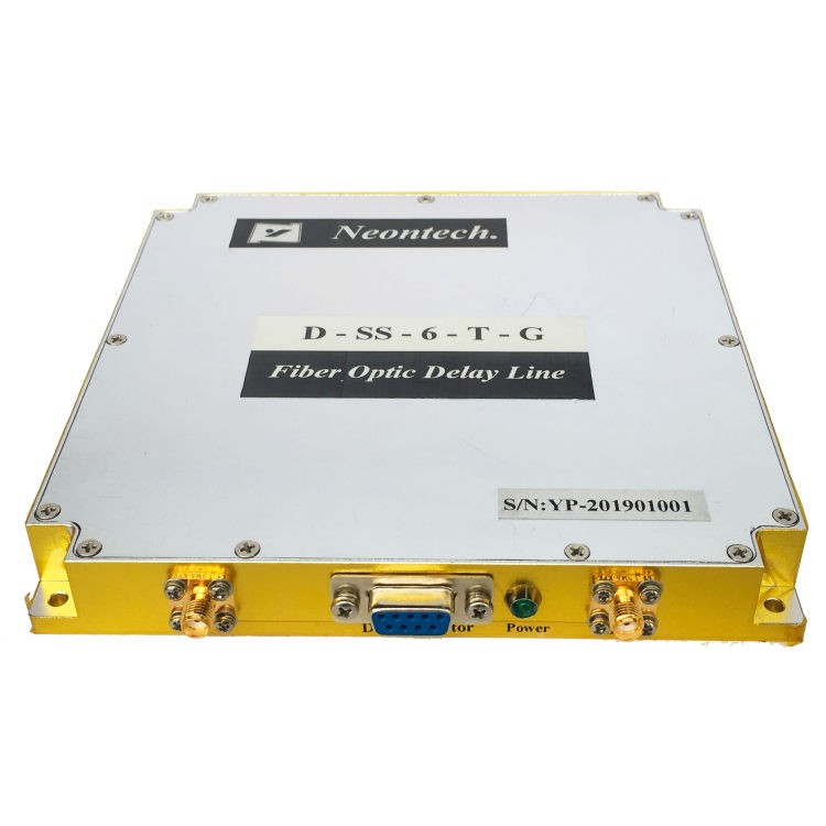
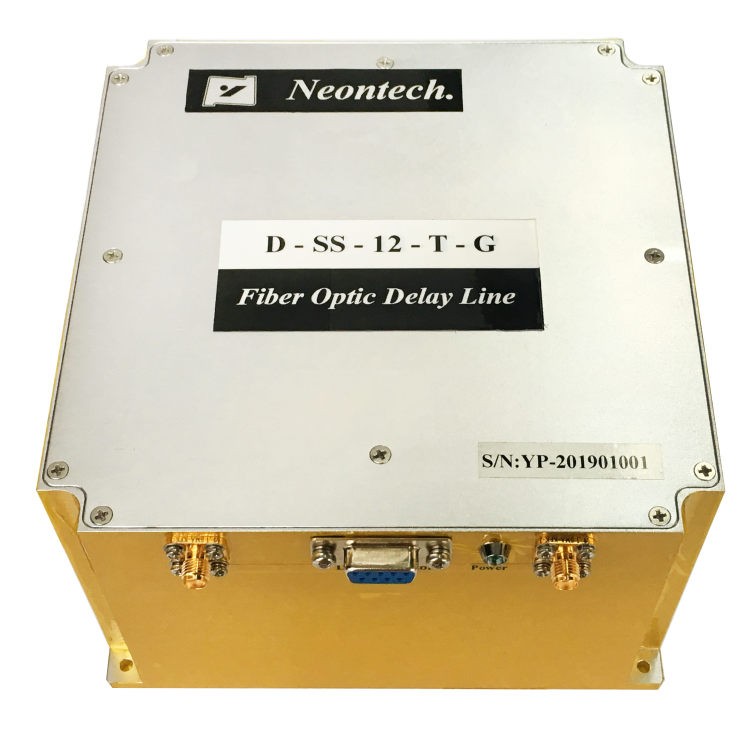
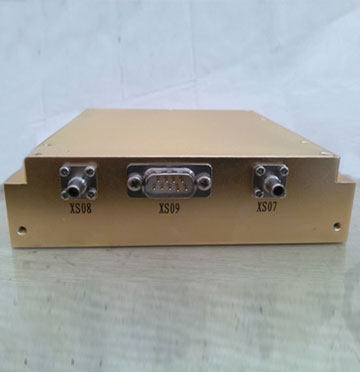
D-SS-18-T Series Optical Fiber Delay Line & Optical Simulator
- Depending on Microwave-photonic technology, the D-SS-18-T series optical fiber delay line & optical simulator delivers unmatched performance for radar testing, signal processing, phased antenna array, antenna simulation, and phase noise testing.
- It works effectively in the whole S/C/X/Ku band, with less insertion loss, high dynamic range, strong electromagnetic isolation, and triple transit signals that are immeasurable.
Optical Fiber Delay Line & Optical Simulator Introduce
Depending on Microwave-photonic technology, the D-SS-18-T series optical fiber delay line and optical simulator deliver unmatched performance for radar testing, signal processing, phased antenna array, antenna simulation, and phase noise testing. It works effectively in the whole S/C/X/Ku band, with less insertion loss, high dynamic range, strong electromagnetic isolation, and triple transit signals that are immeasurable.
| Optical Fiber Delay Line Features ※ Bandwidth to 18GHz ※ High dynamic range ※ Wide temperature application ※ Low amplitude response | Optical Fiber Delay Line Applications ※ Radar testing/calibration ※ Signal processing ※ Electronic war ※ Phased antenna array ※ Antenna simulation |
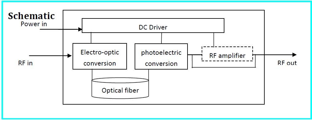
Principle Diagram of Optical Fiber Delay Line
Optical and Electrical Specification (TC = 22±3℃)
| Parameter | Min. | Typ. | Max. | Unit | Remark |
| Frequency Range | 2 | – | 18 | GHz | |
| Amplitude Flatness | – | ±2 | ±2.5 | dB | |
| Time Delay | 0.01 | – | 150 | us | Customized |
| Delay Accuracy | -5‰ | – | +5‰ | – | |
| Insertion Loss | 0 | 20 | 30 | dB | Customized |
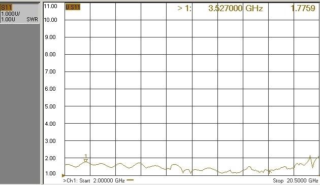
| Input VSWR | – | 1.8 | 2.2 | – | |
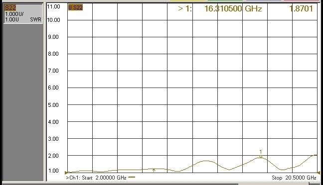
| Output VSWR | – | 1.8 | 2.2 | – | |
| Impedance | – | 50 | – | Ω | |
| Input 1 dB Compression | – | 13 | 17 | dBm | |
| Spurious Signal Rejection Ratio | 60 | – | – | dBc | |
| Noise Figure | – | 50 | 60 | dB | 5us, 25℃ |
| Operate Temperature | -20 | – | 70 | ℃ | See Ordering Information |
| Storage Temperature | -40 | – | 80 | ℃ | |
| Relative Delay vs. Temperature | – | – | 7 | ppm/℃ | |
| Insertion Loss vs. Temperature | – | 2 | 4 | %/℃ |
Power Supply (TC = 22±3℃)
| Pin | 1 | 2 | 3 | 4 | 5 | 6 | 7 | 8 | 9 |
| Voltage | NC | GND | +12 V | NC | |||||
| Rated current | – | – | 0.15 A | – | |||||
| Max Current | – | 1 A | |||||||
Test condition: Vin=+12V
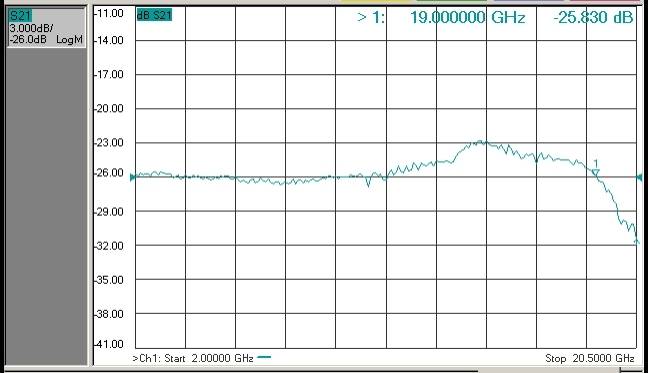
Typical Response Curve
Dimension Unit: mm[inch]
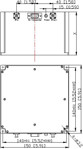
RF Connector: SMA-K(Customized)
DC Connector: DE-9PS(Customized)
Height Value: X (mm)
| Height value: X (mm) | |||||||
| Product Type | D-SS-18-T-G | Remark | |||||
| Time delay(us) | 8 | 20 | 35 | 50 | 60 | 80 | Standard |
| X(mm) | 37 | 50 | 65 | 80 | 90 | 110 | |
| Product Type | D-SS-18-T-P | Remark | |||||
| Time Delay(us) | 8 | 35 | 60 | 80 | 110 | 150 | Compact |
| X(mm) | 20 | 45 | 55 | 65 | 78 | 95 | |
Ordering Information

Sheet 1:
| Symbol | Description |
| D-SS-18 | Fixed fiber optic delay line, Frequency: 2~18GHz |
Sheet 2:
| Symbol | Description |
| T | Time delay , Customized, 0.01 to 150 us |
Sheet 3:
| Symbol | Dimension(refer to Height value: X (mm) ) |
| G | Standard structure |
| P | Compact structure |
| CM | Customized structure |
Sheet 4:
| Symbol | Description |
| I | Industrial grade:Operate Temperature: -20℃ to +70℃ Storage Temperature: -40℃ to +80℃ |
For example: D-SS-18-08-G-I which means fixed fiber optic delay line, frequency: 0.1~6.5GHz, time delay: 8us, standard structure, operate temperature: -20℃ to +70℃, storage temperature: -40℃ to +80℃.
NEON is a force with the highest standard of precision manufacture, quality, and reliability. We have involved rigorous testing at each stage of the project to ensure quality. Besides, NEON has fully embraced the principles of Six Sigma and Lean manufacturing to achieve our goals for operational excellence and ISO 9001 certification.
Warmly welcome to contact us to know more about the optical delay line and visit our factory at any time. Please feel free to let us know if there are any questions in Business.


