How Do Fiber Optic Communication Systems Work?
Fiber optic communication systems have revolutionized the way we transmit information. Unlike traditional electrical cables that use electrical current to carry signals, fiber optic systems utilize light pulses for data transmission. This method offers several advantages, including immunity to electromagnetic interference, reduced signal loss over long distances, and higher bandwidth capacity.
This article will discuss the core components that make up a fiber optic communication system and explore their specific functions.
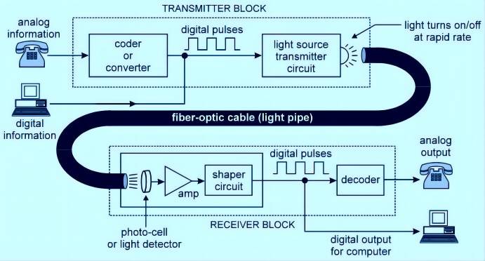
4 Main Components and Their Function of Fiber Optic Communication Systems
1. Transmitter: Converting Electrical Signals to Light Pulses
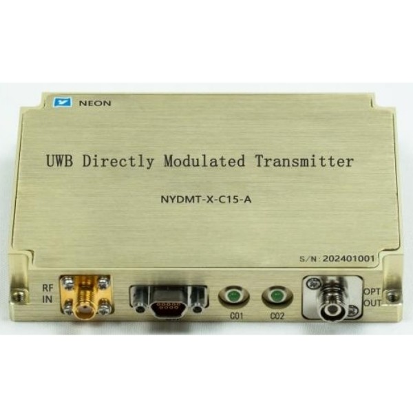
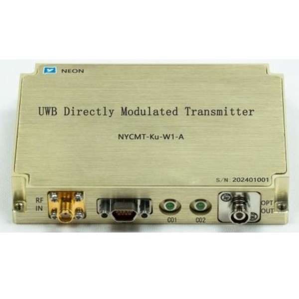
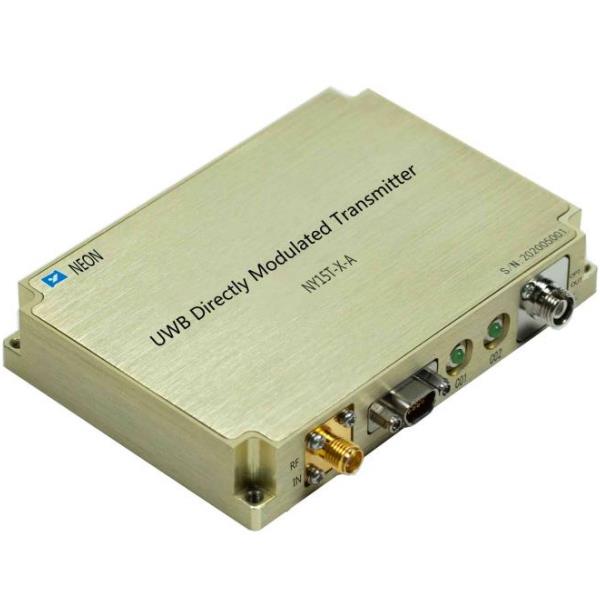
The transmitter is the first component in a fiber optic communication system. It takes electrical signals, which carry the information to be transmitted (like a digital file or voice call), and transforms them into light pulses suitable for travel through the fiber optic cable. This conversion happens in two distinct steps:
A. Electrical Driver Circuit: The electrical driver circuit acts as an intermediary between the electrical input signal and the light source. It receives the electrical signal, typically a series of voltage variations representing the data. The driver circuit then performs two key functions:
- Amplification: The electrical signal received might be weak. The driver circuit amplifies this signal to a higher current level that can effectively influence the light source.
- Modulation: The driver circuit modulates the amplified electrical signal. Modulation refers to the process of varying a specific property (such as intensity or frequency) of the electrical signal according to the information encoded within it. In fiber optic systems, the driver circuit modulates the electrical current in a way that corresponds to the original data.
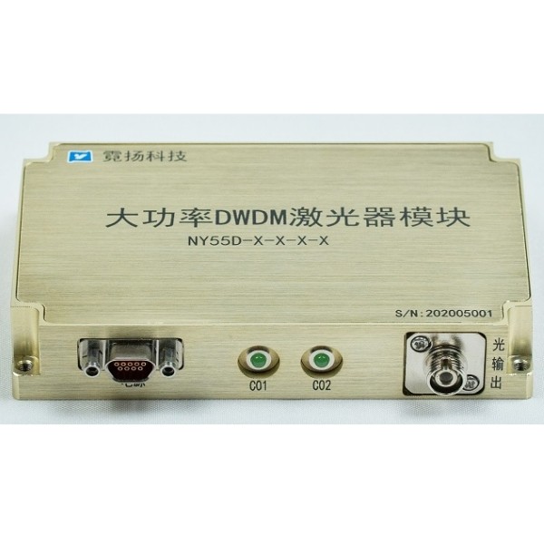
B. Light Source: The light source is the heart of the signal conversion process within the transmitter. It can be either a light-emitting diode (LED) or a laser diode, each with its own advantages and limitations for different applications.
- Light-Emitting Diode (LED): When the driver circuit supplies an electrical current to an LED, it emits light pulses. The intensity of the light pulses can be modulated by varying the strength of the electrical current provided by the driver circuit. LEDs are generally less expensive and have a broader range of wavelengths they can emit compared to laser diodes. However, they tend to produce light with a wider spread, limiting their suitability for long-distance transmission.
- Laser Diode: Laser diodes produce light through a process called stimulated emission. When the driver circuit injects an electrical current into a laser diode, it emits a very narrow, focused beam of light with a specific wavelength. This tight beam collimation allows for longer transmission distances with minimal signal loss. However, laser diodes are typically more expensive than LEDs and require stricter operational conditions.

2. Optical Fiber Cable: The Light Pathway
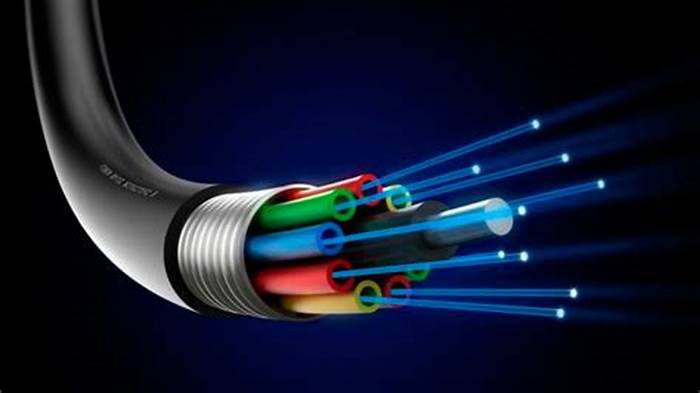
The optical fiber cable is the backbone of a fiber optic communication system. It acts as a long, thin conduit that efficiently transmits the light pulses generated by the transmitter. These cables are incredibly thin strands, typically made of either glass or plastic and are meticulously engineered to guide light signals with minimal loss over various distances.
There are two main types of optical fibers used in communication systems, each with distinct properties that influence their suitability for different applications:
1. Single-mode Fiber
- Core Size: Single-mode fibers have a very narrow core diameter, typically around 9 micrometers (μm) in diameter. This narrow core allows for only one mode of light propagation. A mode refers to a specific path that a light ray can travel within the fiber core.
- Light Propagation and Signal Distortion: Due to the limited space within the core, light travels in a single, straight path in a single-mode fiber. This minimizes signal distortion caused by light rays bouncing off the core-cladding interface at various angles (which can occur in multi-mode fibers). As a result, single-mode fibers offer superior signal transmission quality and can achieve longer transmission distances compared to multi-mode fibers.
2. Multi-mode Fiber
- Core Size: Multi-mode fibers have a larger core diameter compared to single-mode fibers, typically ranging from 50 μm to 100 μm in diameter. This larger core diameter allows for multiple modes of light propagation within the fiber.
- Light Propagation and Signal Distortion: Light rays in multi-mode fibers can travel along various paths due to the larger core size. Some rays travel more directly through the core, while others bounce off the core-cladding interface at different angles. This variation in light ray paths can cause signal distortion, especially over longer distances, as the light pulses arrive at the receiver at slightly different times.
- Advantages and Trade-offs: Despite the signal distortion limitations, multi-mode fibers offer certain advantages. Their larger core diameter makes them easier to connect with light sources and detectors, allowing for simpler and potentially lower-cost installations. However, their susceptibility to signal distortion restricts their transmission distances compared to single-mode fibers.
3. Optical Amplifier: Signal Regeneration for Extended Distances
In long-distance fiber optic communication systems, light signals experience attenuation (weakening) as they travel through the fiber optic cable. This attenuation occurs due to various factors such as absorption and scattering within the fiber core. As a result, the signal strength can deteriorate significantly over long distances, potentially hindering accurate data reception.
To compensate for this signal loss and ensure the light signal reaches the receiver with sufficient strength for proper decoding, an optical amplifier can be strategically placed within the transmission path. Unlike traditional electronic amplifiers that operate on electrical signals, an optical amplifier directly amplifies the light signal itself.
Here’s a breakdown of how an optical amplifier functions:
- External Energy Source: An optical amplifier requires an external energy source, typically a laser diode operating at a different wavelength than the signal light.
- Stimulated Emission: The external laser light pumps energy into the doped material within the optical amplifier. This doped material contains rare earth elements that can be excited to higher energy states by the pump laser light.
- Signal Amplification: When the excited atoms in the doped material return to their ground states, they release energy in the form of light. This emitted light has the same wavelength as the signal light traveling through the amplifier. By carefully controlling the interaction between the pump light, the doped material, and the signal light, the optical amplifier can amplify the weak signal, essentially boosting its intensity.
By incorporating optical amplifiers at specific intervals along long-distance transmission lines, fiber optic communication systems can maintain strong signal integrity and enable reliable data transmission over vast distances.

4. Receiver: Reconverting Light Signals into Electrical Signals
The receiver station sits at the destination end of the fiber optic communication system. Its critical function is to convert the received light pulses back into electrical signals. These electrical signals can then be processed and interpreted by electronic devices. This light-to-electrical conversion is achieved using a photodetector, which is typically either a photodiode or an avalanche photodiode.
- Photodetector: When light pulses from the optical fiber cable reach the photodetector, a crucial phenomenon occurs. The photodetector material absorbs the energy within the light pulses. This light energy can be in the form of specific wavelengths depending on the modulation scheme used by the transmitter.
- Light Absorption and Current Generation: The absorption of light energy by the photodetector material causes the creation of electron-hole pairs within its internal structure. An electron-hole pair consists of an electron excited to a higher energy level (leaving a “hole” where it originally resided). In essence, the absorbed light energy disrupts the electrical balance within the photodetector.
- Current Proportionality: The photodetector is designed to allow these generated electron-hole pairs to conduct electricity. The flow of these electrons creates a weak electrical current at the output of the photodetector. The strength (amplitude) of this electrical current is directly proportional to the intensity or frequency of the received light pulses. In other words, variations in the intensity or frequency of the light pulses (which encode the information) are reflected in corresponding variations of the electrical current generated by the photodetector.
- Electrical Amplifier: The electrical current produced by the photodetector can be very weak, especially for signals that have traveled long distances. To ensure sufficient signal strength for proper processing by electronic equipment, an electrical amplifier circuit may be included within the receiver. This amplifier electronically increases the amplitude of the weak current from the photodetector to a level suitable for further processing.
Conclusion
Each component within an optical communication system plays a critical role in ensuring the successful transmission of information. The transmitter efficiently converts electrical signals into light pulses, the optical fiber cable guides these light pulses over long distances, the optional optical amplifier boosts the signal for extended reach, and the receiver meticulously converts the received light pulses back into electrical signals, completing the information transfer process. The synergy between these components makes fiber optic communication systems a powerful and reliable method for data transmission across various applications.


