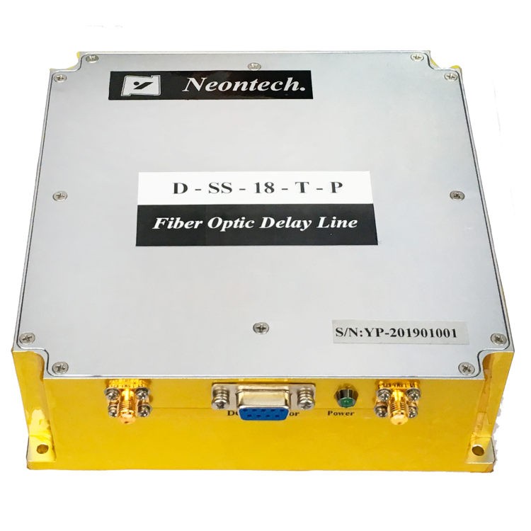
NY062 series Millimeter Wave Broadband Delay Line
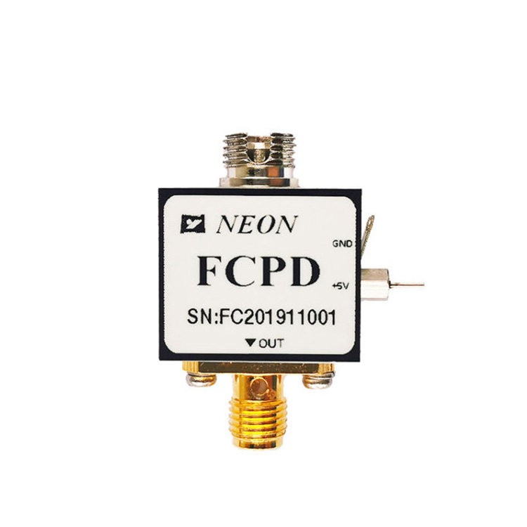
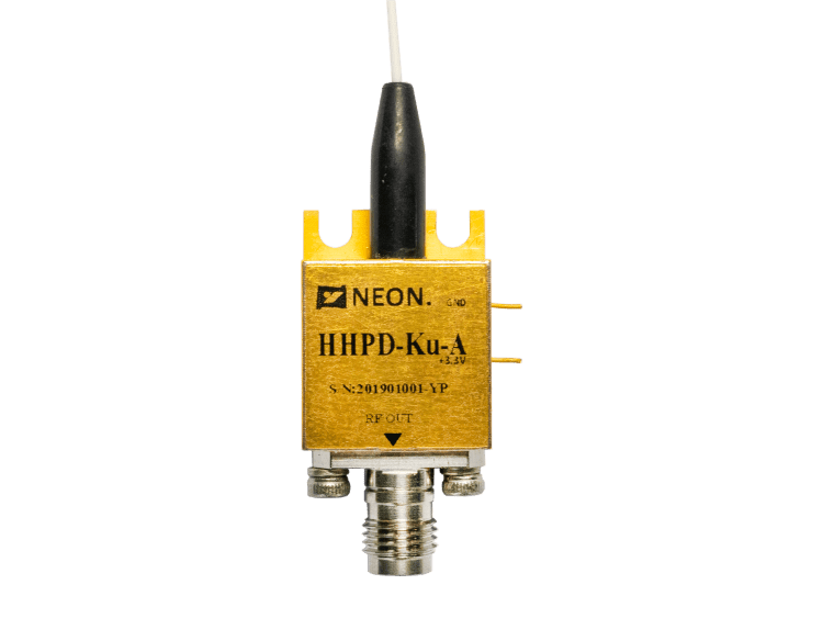
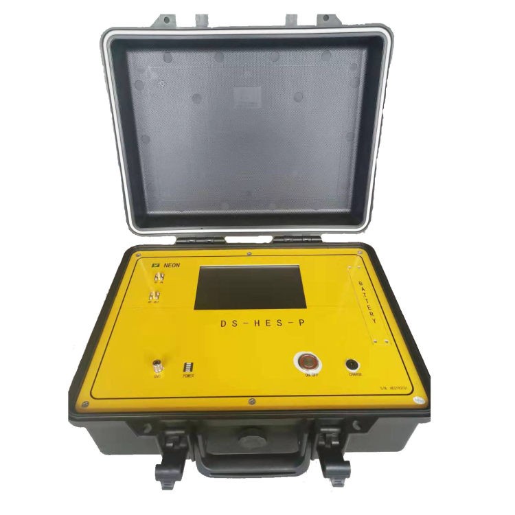
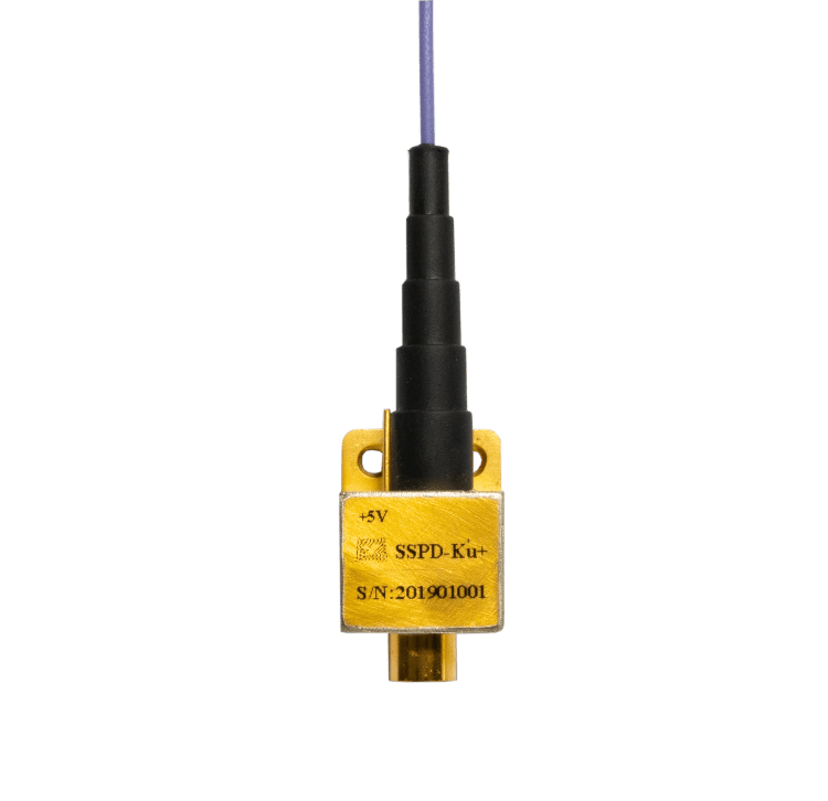
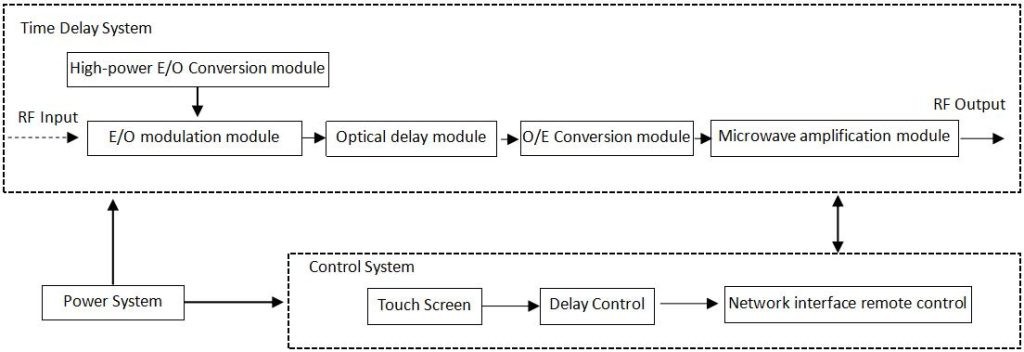
- Mainly composed of a high-power electro-optical conversion module, electro-optical modulation module, optical fiber delay module, photoelectric conversion module, delay control and visual touch screen system, network remote control system, RF input/output interface, and power supply system, etc.
- The main function is to delay the millimeter wave signal received by the radar(The specific delay can be set on the touch screen) and then input it to the receiving system of the machine room.
- Due to the natural ultra-strong anti-interference ability of optical fiber communication, it can avoid the interference of spatial leakage signals caused by traditional cable delays. Based on this anti-interference characteristic, the receiving system can obtain a reference signal that is closest to the radar-transmitted signal, thereby accurately calibrating the system.
- Input signal: common ground radar pulse, continuous wave signal, pulse group, or pulse rapid frequency conversion signal.
Feature
- Controllable delay
- High stepping accuracy
- Low signal distortion
- Millimeter wave Ultra wideband
Application
- Radar simulation
- Signal processing
- Electronic war
Schematic

Electrical / Optical Characteristics
| Parameter | Value | Unit | Remarks | ||
| Min | Typ. | Max | |||
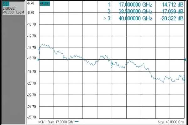
| Frequency | 17 | – | 40 | GHz | – |
| Flatness | – | – | 2 | dB | Within any 2GHz bandwidth |
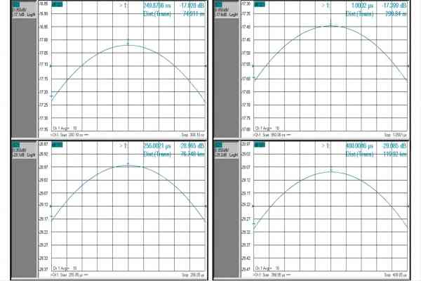
| Time delay | 0.25 | – | 400 | us | – |
| Altitude | 37.5 | – | 60000 | m | – |
| Time delay step | – | 0.25 | – | us | – |
| Altitude step | – | 37.5 | – | m | – |
| Time delay accuracy | – | – | 0.05% | – | – |
| Insertion loss | – | – | 40 | dB | – |
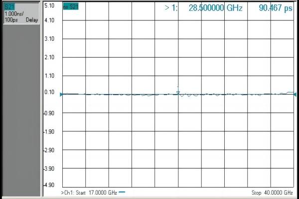
| Group delay fluctuations | – | – | 1 | ns | K or Ka band |
| – | – | 2 | ns | Full frequency band | |
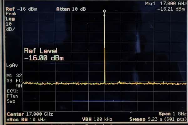
| Clutter rejection ratio | 60 | – | – | dBc | – |
| Harmonic suppression ratio | 30 | – | – | dBc | – |
| Maximum input power | – | 15 | dBm | – | |
| Pass-through suppression | 60 | – | dBc | – | |
| VSWR | – | – | 1.4 | – | 50Ω,Full frequency |
| Working temperature | -10 | – | 35 | ℃ | – |
| Storage temperature | -20 | – | 45 | ℃ | – |
| Connector | Type K | ||||
| Power supply | 220VAC/50Hz | ||||
Display function
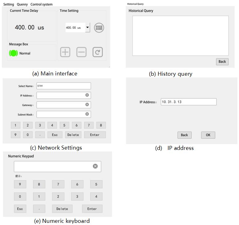
|
Item |
Functional Description |
|
Query |
Enter the history query interface, and display the history record. As shown in Figure b. |
|
Settings |
Enter the network setting interface (Figure c) to set the local IP address, gateway, and subnet mask |
|
Control System |
Connect to the background program to set up the background IP address. As shown in Figure d. |
|
|
Displays the current delay status. Press “ |
|
|
Enter the numeric keyboard interface and set the delay. As shown in Figure e. |
|
|
Increase by step of 0.25us over the delay time currently displayed |
|
|
Step is reduced by 0.25us based on the currently displayed delay time |
|
|
The delay time can be set to the value displayed in the current display box “ |
|
|
Delay state was set successfully |
|
|
The delay state setting is abnormal |
Typical curve
Dimension and Interface
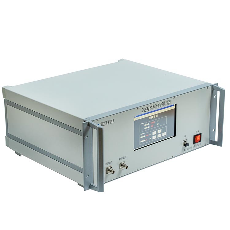
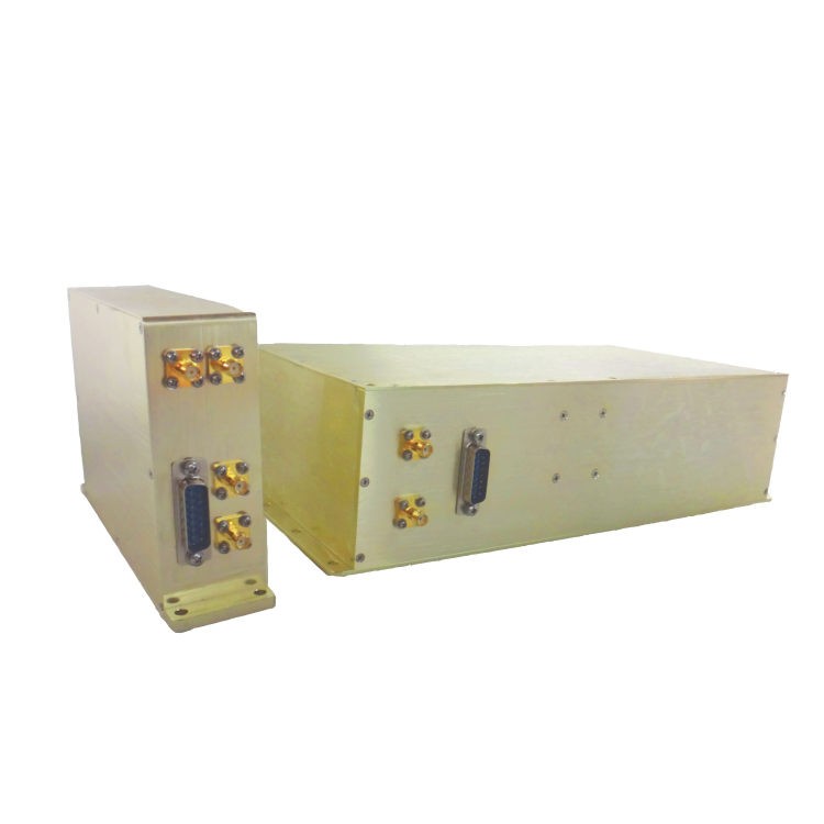
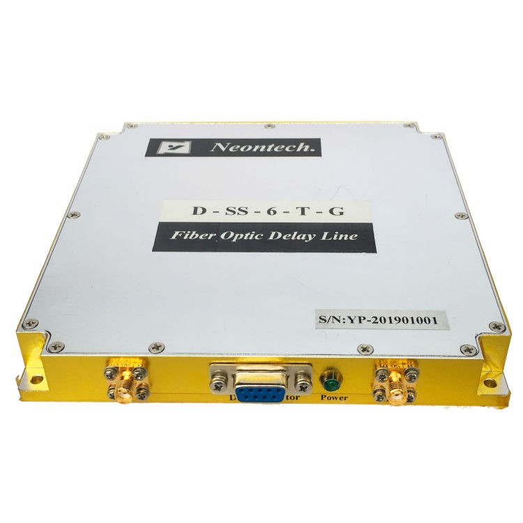
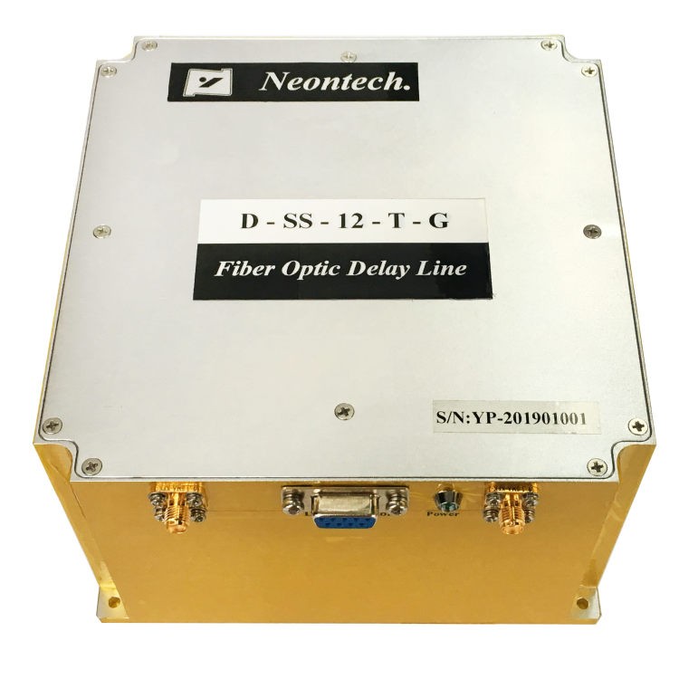
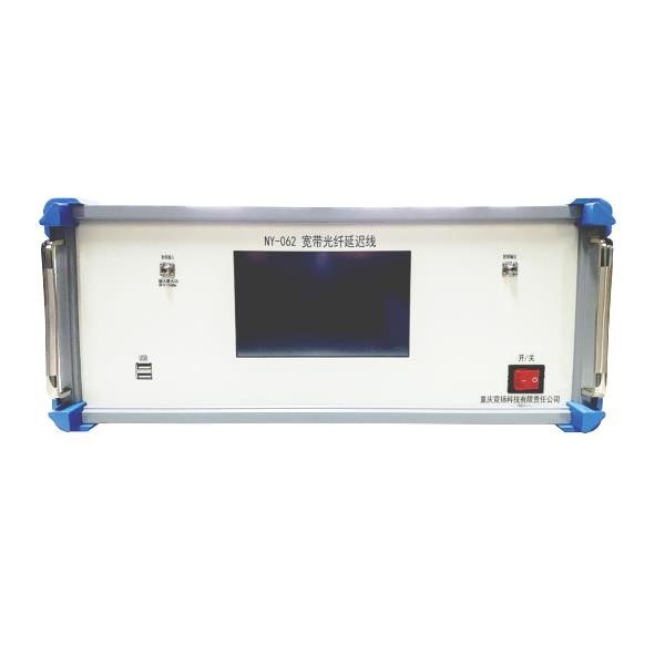
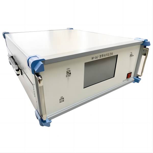
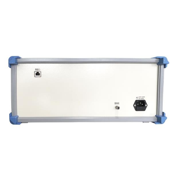
NY062 millimeter wave broadband delay line integrated into a standard 19-inch 4U chassis. The chassis is made of aluminum alloy, and the middle of the front panel is a touch screen, which can display the current delay state and realize the switching function of the delayed state.
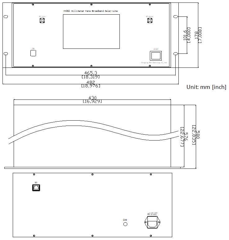
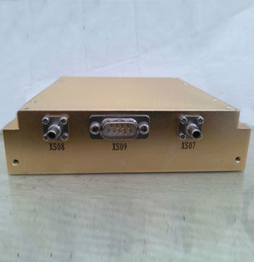
| Interface definition of NY062 Series | |||||||
| Interface | RF input | RF output | USB |
ON/OFF
(Power)
|
WN
(Network interface)
|
GND |
AC
(Power interface)
|
| Interface Type | SMA-K | SMA-K | Type -A | SPST KCD 4 | YT-RJ45 | M6 | 220V/AC |
This series of products are customized, and the product information in this article is for reference only.



 ” to display and quickly select the delay time set for the last 5 times


